Blocking Capacitors
by Carl Walker
A blocking capacitor is a capacitor used to block DC current while allowing AC current. When used in a Common Emitter Amplifier, this prevents the DC bias set from interfering with the AC input signal to be amplified. The value for the blocking capacitor is determined by a rule-of-thumb.
The rule-of-thumb is this. The blocking capacitor's reactance should be 10% of the value of the resistance set up in the bias. Reactance is frequency-dependent, so a good blocking capacitor for an audio amplifier (20Hz - 20kHz) is different than that used for radio (100kHz).
To see a blocking capacitor in action, I'll analyze a Voltage Divider Bias (VDB) Common Emitter Amplifier from a popular video from the W2AEW YouTube channel.
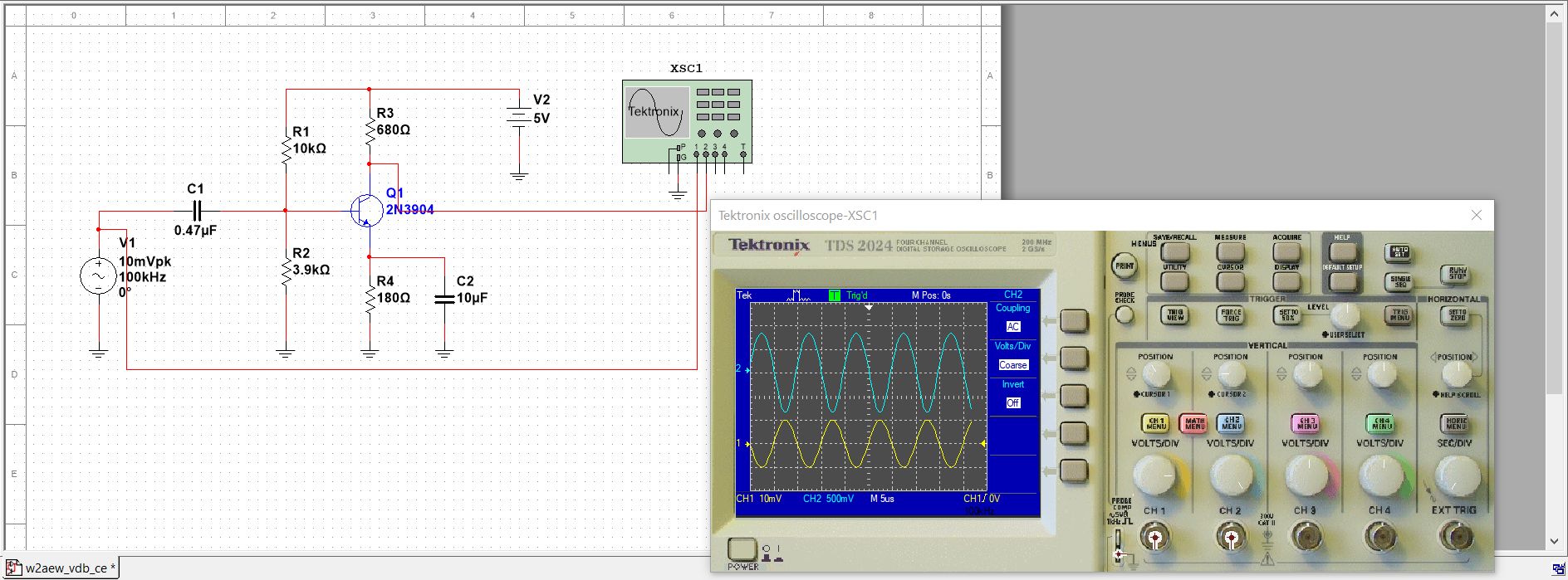
Here is the circuit.

The designer has chosen a blocking capacitor value of 0.47μF. To verify that the selection is adequate, let's find the input impedance of the amplifier. For the AC analysis, the DC voltage of 5V connected to R1 goes to ground. The bypass capacitor is a short, leaving the AC resistance on the emitter leg (r'e).
To calculate the AC Emitter Resistance, first find the voltage at the base of the transistor VB. Subtract off the fixed VBE of 0.7 V and get the voltage at the emitter VE.
	VB = 5 V * 3.9 kΩ / (10 kΩ * 3.9 kΩ) = 1.4 V
	VBE = 0.7V
	VE = VB = VBE = 1.4 V - 0.7 V = 0.7 V
	IE = 0.7 V / 180 Ω = 3.9 mA
	r'e = 25 mV / 3.9 mA = 6.41 Ω
The "25 mV" is from the formula for AC Emitter Resistance.
Using a Beta of 100 for the 2N3904, R1 || R2 || βr'e = 522 Ω. With our 10% rule-of-them, we want the reactance XC no larger than 10% of 522 Ω.
Here's the check. The frequency is 100 kHz or 10 * 103 Hz.
  XC < 0.1 * R
  1 / ( 2 * π * 100 * 103 * 0.47 * 10-6 ) < 0.1 * 522
  3.39 < 52.2
So, we're under the maximum reactance. The base gets all of the AC voltage. What would a bad value look like? Suppose the capacitor is 1 pF. In that case, the formula would yield a 1.59 MΩ reactance.
  XC = 1 / ( 2 * π * 100 * 103 * 0.1 * 10-9 )
  XC = 1.59 MΩ
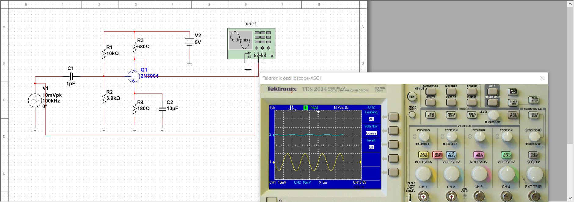
This means that -- at this frequency with this smaller value -- the capacitor will get all the voltage as it overwhelms the R1 || R2 || βr'e. Let's check this with Multisim. This is a version of the circuit with an inadequate capacitor.

Notice in the oscilloscope, that the scale is set the same for both channels. Very little signal appears at the collector which is of course the opposite of what we want in an amplifier!
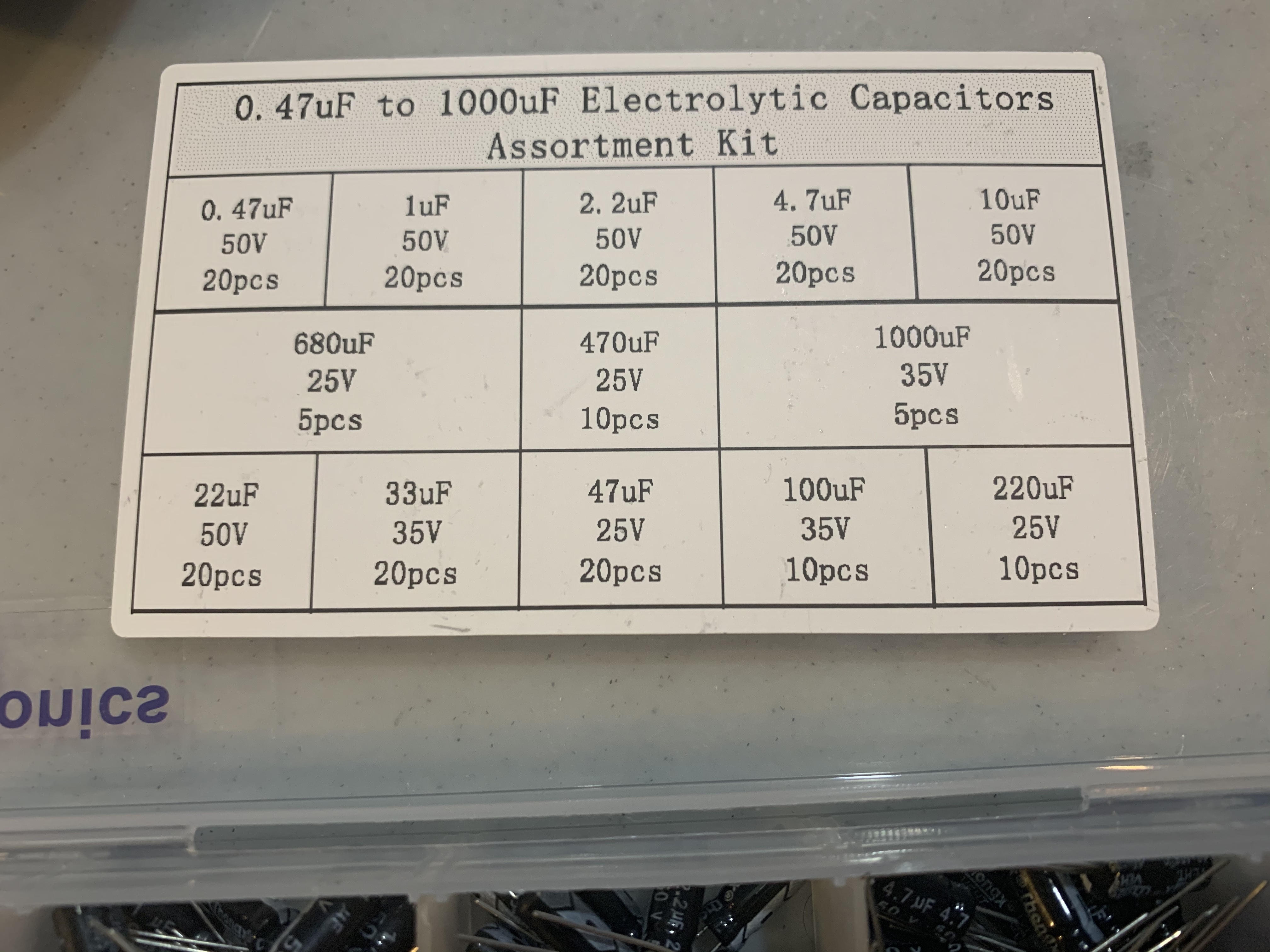
New to electronics, when I first viewed the YouTube video, I immediately asked "0.47 What?". I noticed in the comments that a few others had similar question and were looking for guidance on selecting the caps. Keep the 10% rule-of-thumb in mind and with this analysis you should be able to find a match in a kit like this.
